
Table of Contents
OmagCUT
V. 2.3e1
Omagcut is our advanced bridge cutting software developed for usage with 5 Axes Cnc Cutting Centers.

In order to launch this software the user have to click the icon link.
IMPORTANT: Not every function described in this manual is always available on the software. Functionalities depends from the user license and the utilized machine.
Omagcut Introduction
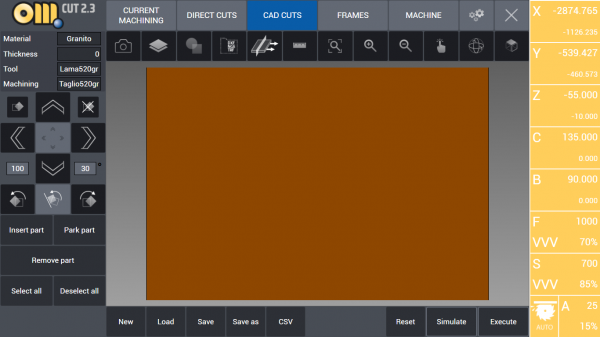
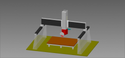
This is the software interface when you launch Omagcut. Now we will explain any aspect and any possibility given to the user.
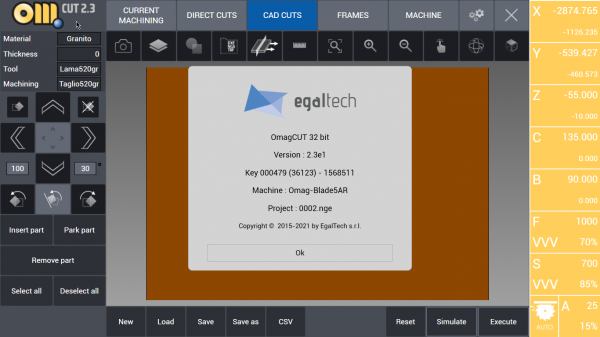
By clicking the logo in the top left corner it will be shown a new window containing the software version along with the key, the machine set and the copyright details. This window will be closed by clicking “OK”.
MAIN MENU
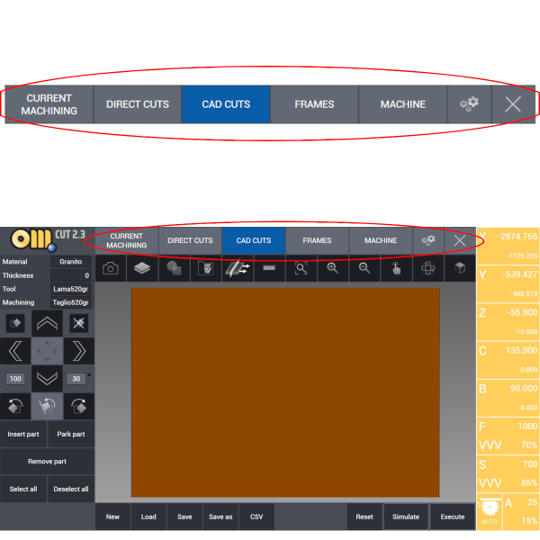
At the top margin of the interface are located the buttons used to navigate the software functions. Each section will be analyzed and explained.
Table
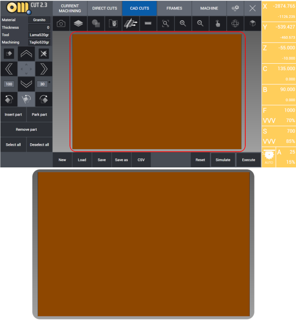
The brown region in the middle of the interface represents the machinery worktable. Therefore it is dimensioned exactly as it, depending from the machine.
Here the user can work and preview any slab, project or part to be cut. Also, work simulations are done here and the user can create cutting programs and blade or milling tool paths.
Project/Slab definition
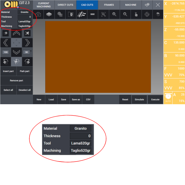 Under the logo in the top left corner is displayed a window that allow the user to know the main specs of the current project.
More specifically, in this box the user can find:
- Material: define the material to be worked (Granite, Marble, Ceramic, …)
- Thickness: define the thickness of the material (expressed in millimeters)
- Tool: specify which tool is used (Saw, Mill, Drill, …)
- Machining: set the kind of cut or machining made by the tool
HOW TO: Define new raw slab
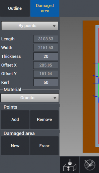
 Raw Stock Definition: This button opens a new page where is possible to define width, lenght, thickness and kerf of the slab currently on the table. It is also possible to define damaged zones on the slab which will not be cut due to cracks, imperfections or colours. Here is displayed the Raw Stock Definition page: divided in two tabs, Outline and Damaged Area which allow the user to set the parameters relatives to the current slab. It is also possible to specify the current slab's material and draw on the screen the damaged area.
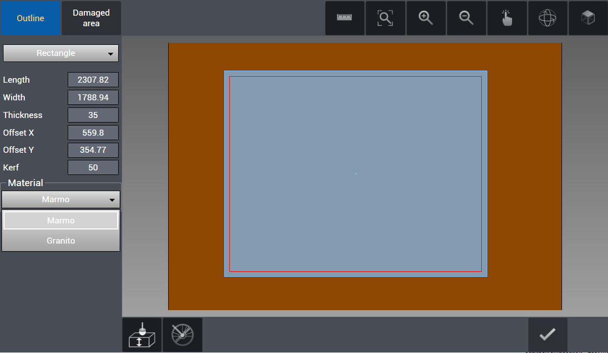
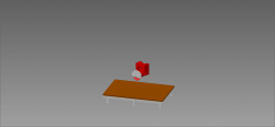
By pressing the Raw Slab button it is possible to define the specifications of the slab on the work table. Material outline can be drawn by three different methods:
- Rectangle: Slab Length – Width – Thickness values can be entered in mm units. Distance from lower left corner of work table can be measured by a meter precisely to lower left corner of slab in X and Y axes and these measurements can entered to Offset X and Offset Y boxes. In this way slab position is defined parametrically. Kerf value is the clearance value in mm from sides of the slab. After a value is entered in Kerf box, a working perimeter is drawn in red offset by that value from the sides. Slab that is defined as rectangle can be modified also by pressing and dragging the sides, can be moved by panning, this is especially useful for machines on which camera option is available so that drawing overlaps slab image.
- By Points: In the program corners of the slab can be pinned by mouse. If this method is preferred, every pinned corner points are connected by linear lines and a closed cutting geometry is formed.
- From Laser: By the help of point laser mounted on the machine, corners of the slab can be pinned. If this method is preferred, every pinned corner points are connected by linear lines and a closed cutting geometry is formed.
The material of the slab has to be defined. Usually it is marble, granite or quartz.
HOW TO: Capture slab image
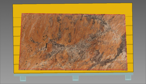
 Camera: This button is used to take a photography of the slab currently on the table and show it on the screen. This function does help when positioning parts that will be cut inside the slab since it allows to preview the aspect of the material that will be cut. This is also helpful when orientating parts inside the slab with respect to vein match.
HOW TO: Define damaged area
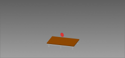
Once the slab is correctly declared and defined, it is possible to add any damaged areas on it which will prevent that area to be cut. This can be done giving the outline points of the damaged or imperfect area directly on the slab or by laser which will be marked by a red line. If the nesting function will be used, no part will be put inside the damaged area.
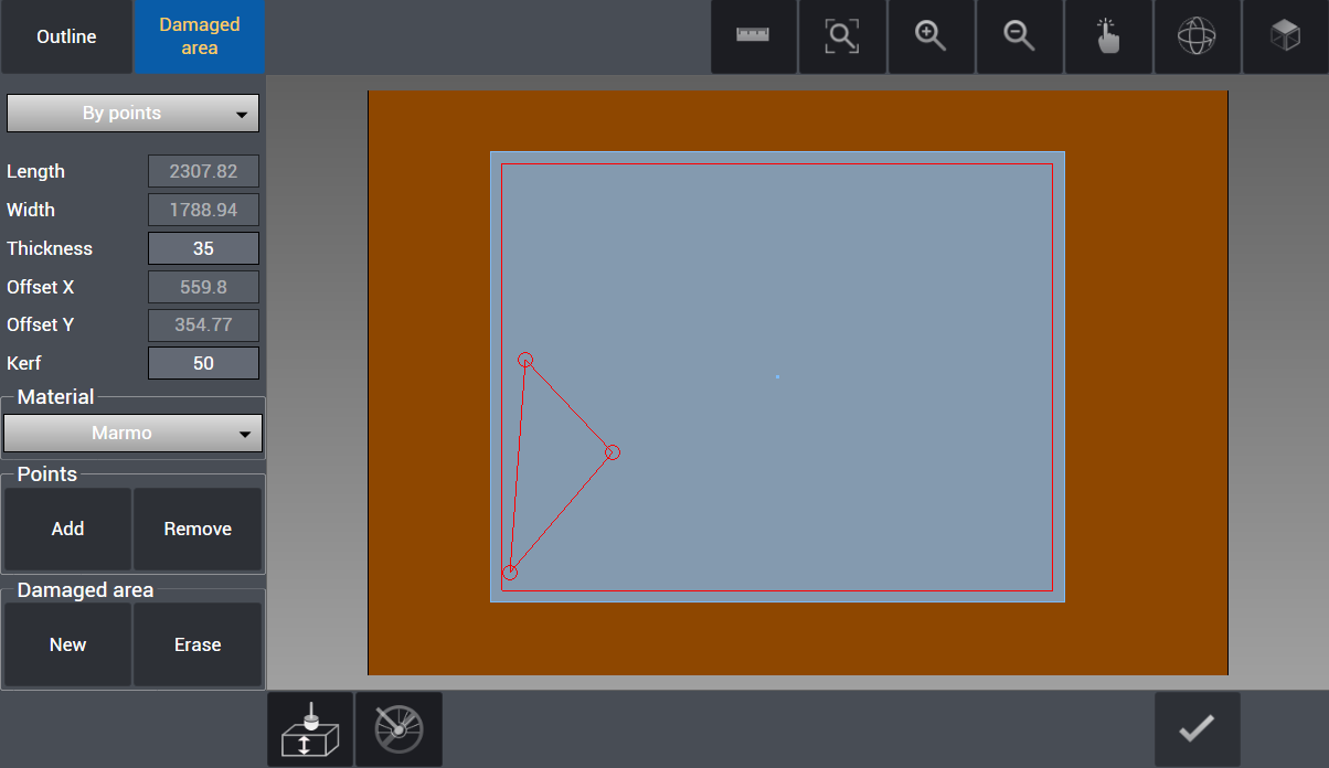
After the slab and, if present, any damaged area has been defined, the user can confirm the creation of it by pressing the confirm button on the bottom right of the screen. A damaged area prevents any part to be cut on it.
HOW TO: Use Plan Probe
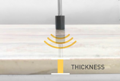
 If the machine has this option, a mechanical probe can be used to check the real stone thickness.
In order to execute this function, the button with plan probe icon as below is pressed and after probing is realized automatically by the machine, thickness value is updated with real value. It is vital to execute this function especially before 45° angled and mitre cuts.
Raw Slab Confirmation
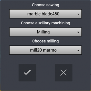 After the slab is defined with its dimensions, thickness and if necessary its damaged areas declared, we press the confirm button on the bottom right of the screen. Doing so will open the last confirmation window. It's possible to choose the sawing tool from the Tool DB and if present the auxiliary machining and its specific tool.
WARNING: If the machine doesn't have a blade fit for the chosen material (for example Granite) when confirming the slab, there will be no one choice of blade under “Choose sawing”. It's necessary to go in the Machine section of the software and select a blade fit for the desired material, making sure that its machining suit the current slab.
Current Machining
Used to observe and monitor the real-time movements and cuts of the machine through the 3D simulation from screen.
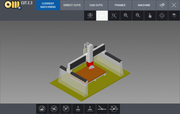
 Eye: This button allows the user to change view of the machine:
1) Full machine 2) Head, tool and table 3) Only tool and table
CAD View Tab
Those buttons are available in all of the software's functions.
 View All: This button is used to center the current view in order to display the entire project. It overwrite any previous zoom and/or view of the project.
 Zoom In: For every click this button enlarge the project view, zooming in the working table.
 Zoom Out: For every click this button reduce the projecxt view, zooming out the working table.
 Move: By pressing this button, the user perform the translation of the project view. After clicking it is possible to move the view by holding the left mouse button.
 Rotate: This button gives the command to freely rotate the project point of view. Once it is activated just press the mouse left button and move it.
 Top View: Set the project view directly from above.
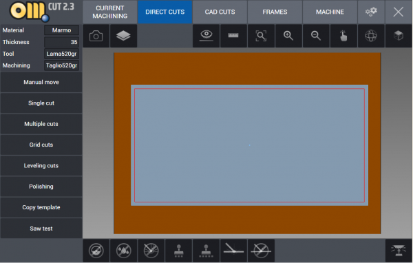
Direct Cuts
Direct Cuts are cutting operations which can be realized by the operator directly by saw, drawing on display or utilizing reference points marked by laser on the machine. They are used to perform manual cuts directly, of any kind: single cuts, multiple cuts and more.
Manual Move
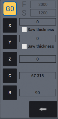 This function is used on the machine to move manually the head. The user can use this in order to position the tool in a desired position when it's necessary.
With G0 button active and pressed, the incremental value that is entered in axis field X Y Z C B becomes active when pressed relevant axis box and the machine moves in that axis by the incremental value entered. If G0 button is not active, feed F (mm/min) and speed S (rpm) parameters become active and it becomes possible to do cut during manual movement.
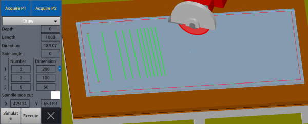
Single Cuts
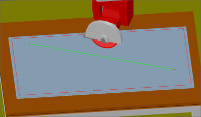
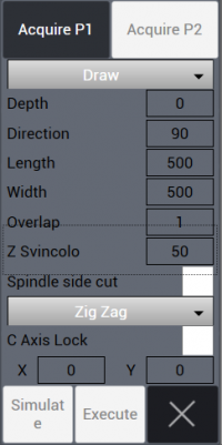
 With this button the user can perform a cut from a point P1 to a point P2 of the slab. In order to do so the two points are to be defined by specifying the coordinates in the box OR by acquiring those coordinates directly on the slab, drawing them. In example we have a cut connecting two drawn points on the slab.
Multiple Cuts
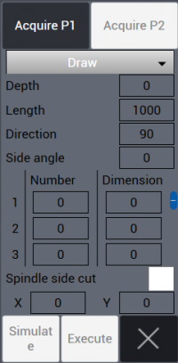 This function is similar to the Single Cuts one. But here the user can set a number of cuts to be repeated, parallel to the first, with a defined distance for each set of cuts. In example we can see a multiple cut with differents distances: 2 cuts distanced 200 mm, then 3 with a distance of 100 mm and finally 5 cuts with a distance of 50 each other.
Grid Cuts
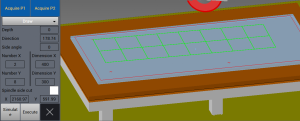
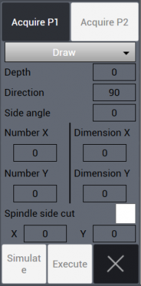 After single cuts and multiple cuts there is the Grid cuts function. With this the user can perform many cuts disposed in a grid pattern by specifying the number of X and Y repetitions and the distances between them. In the example below we have created a grid with two X repetitions at 400 mm distance and 8 Y repetitions with 300 mm distance each others.
Leveling Cuts
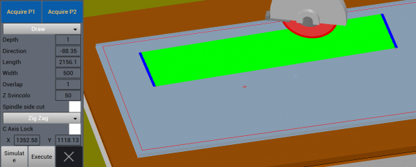
 This kind of cuts is for leveling purpose. The user choose a line between two points, like in the single cuts function, then specify direction, lenght and widht of the desired leveling. In the example we have a 1 mm depth, 2156.1 mm long and 500 mm wide leveling cut.
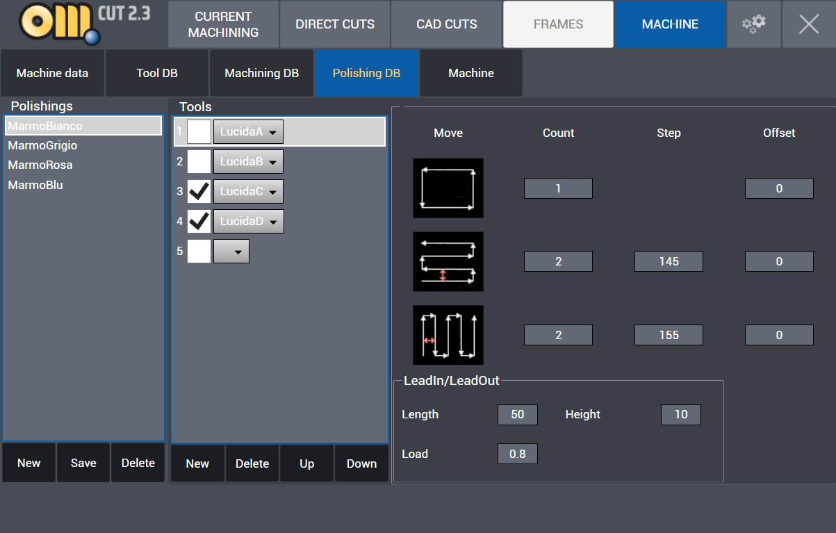
Polishing
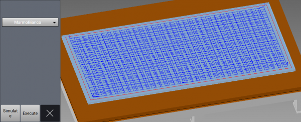 The polishing function is used to polish the surface of the slab. The parameters are set from the Machine section of the software, under “Polishing DB”. In the example there is displayed the “Marmo Bianco” polishing.
Copy Template
 This function allow to mark points on the table.
There are three ways to add points:
- Drawing them
- Laser
- Saw
Points that are marked by one of the methods above are connected in lines or arcs enabling copying of simple templates on work table.
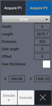
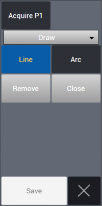
Saw Test
 This function is designed to test the right setup of the machine, head and tool and it is done by drawing a line from a point P1 to a point P2. Saw blade cuts a straight line by rotating the head + / - 180° so that width of gap between two cuts can be checked to be thickness of the blade.
There are three ways to add points:
- Drawing them
- Laser
- Saw
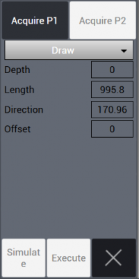
The test consists in performing half cut in a direction and the other half in the opposite direction, rotating the tool by 180°. Of the two points marked by one of these three methods, it is possible to choose only one point and enter cutting parameters from relevant menu.
- Depth : Cutting depth (mm).
- Length : Cutting length (mm).
- Direction: Angular cutting direction ( ° ).
When pressed Simulate button below, simulation of cutting is visualized. When pressed Execute button below, cutting becomes active on the machine.
Cad Cuts
This is the environment where the user can create drawings and cutting lists in order to generate the machine program, and it is possible to import DXF files.
Visual Management and Machining Tab
Below the main tab we can find the set of buttons designed for visual management and, if the user is in the CAD CUTS area, more buttons to manage the cutting and machining:
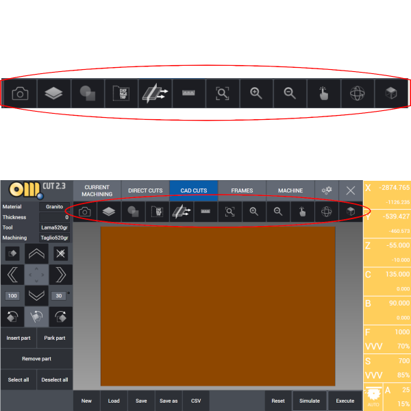
Camera: See How to: Capture slab image.
Raw Stock Definition: See How To: Define New Raw Slab.
 Parametric Geometries: This button is used to create geometric shapes whose dimensions can be modified by the user. Kitchens and bath tops can be created with this function.
See How To: Create Parametric Geometries.
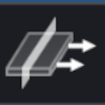
 Import from File: It is possible for the user to import DXF files containing project and drawings created in Autocad or other softwares. It is also possible to import NGE and TRF formats. From the left column, directories where the files are located can be opened, from the directory relevant file to be worked is selected and on main panel selected file and its components are viewed on a grid.
 Machining Managing: This button open the machining tab. Here it is possible to oversee the blade cuts and drilling/milling tool paths and more specifically to monitor the saw cutting path order. It is also possible to move and separate parts that are cut from each other with the vacuum movement system.

 Ruler: With this button the user can make a linear measurement between two points on the table. That measure is displayed in a box at the left bottom corner of the software interface as shown on the right.
NOTE: Look to Cad View Tab for the description of the other viewing buttons.
Directional Buttons
Under the Project Specs box there is the set of directional buttons used to move the selected parts on the worktable. The movements can be linear or rotational. Let's sum up what these buttons do.
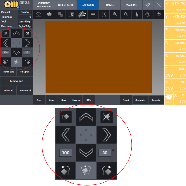

Those two buttons are used to enable or disable the auto-rotate feature for the parts of the automatic nesting. After the left one is pressed, the selected parts can rotate freely depending on the automatic nesting choice. On the other hand, after pressing the right button the selected parts cannot be rotated by the nesting, which will organize them on the slab as they were oriented out of the worktable.

The four directional buttons allow the selected part to be moved on the X or Y axes for the distance specified in the apposite box (expressed in millimiters) down on the left for every click.

The central button allows the user to switch between two translation modes: if it is activated, when a directional button is pressed the selected part is moved on the slab to the extreme position following the button's direction. Otherwise, if that button is not active, the part is moved by the distance specified in the field on the left, expressed in millimiters, wich can be modified by the user.
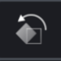

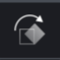
This set of buttons allow the user to manage the rotations of the selected parts. In the field with the angle (expressed in grades) it will be set the desired angle of rotation. Then using the clockwise or the counter-clockwise buttons it's possible to rotate the parts. The button in light grey is used to force the magnet function between different parts, aligning a part on the side of another part.
Part Manager
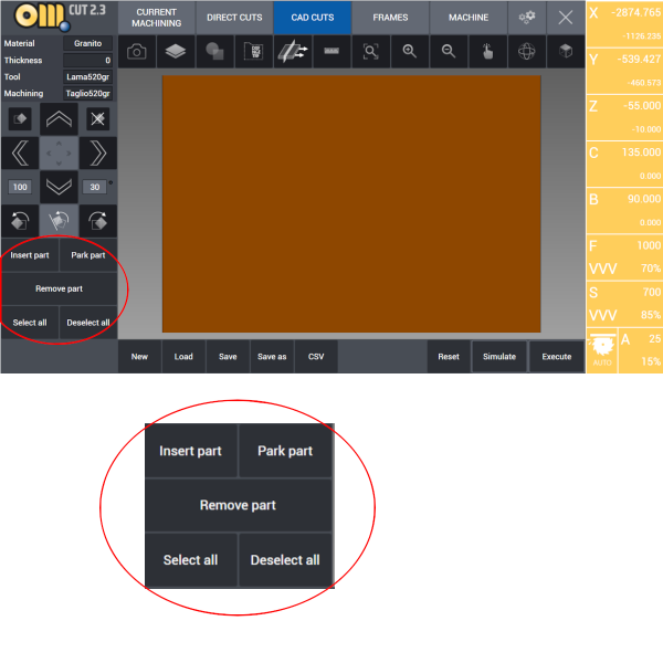 In the bottom left corner of the interface there are some buttons wich allow the user to manage the parts contained in the project.
- Insert part: this action proceed to insert a selected parked part on the slab. It works both on single parts and with multiple selection of parts.
- Park part: the part or parts already located on the slab can be parked outside of it by pressing this button.
- Remove part: All parts selected are removed from the project and therefore erased.
- Select All: As the label say, this button allow to select all the current parts in the project.
- Deselect All: The opposite of “Select All”, this button will deselect any selected part if there is any.
File and Machining Management Tab
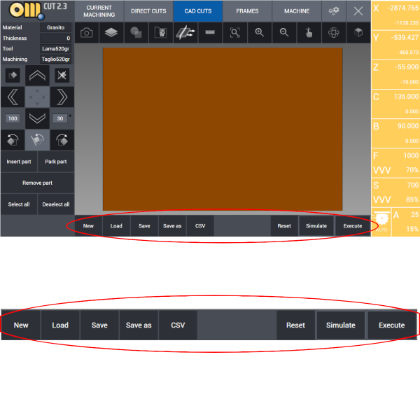
- New: Ask to the user if changes to the current project are to be saved and then close it.
- Load: Open the folder “my projects” in the OmagCUT directory and let the user choose a project to load.
- Save: Save the current open project in the current directory.
- Save as: Save the current open project as with a new name in a chosen directory.
- CSV: This function enables the import of parts cutting list prepared in a specific format from Excel to OmagCut.
- Reset: Proceed to cancel all the operations and all the parts on the table.
- Simulate: It enables graphic 3D simulation of machining process using the machine 3D model which reproduces the table, the motors, the blade, the tools, slab and the parts.
- Execute: This button starts the execution of the given cutting and machining on the work table.
WARNING: It is strongly recommended to check machine movements and cutting tool path with the simulation function before the execution of any program.
Work Parameters
There are many useful information in the right column of the interface such as machine real coordinates, movements, blade or tool feed, RPM of the machine and ampere comsumption values.
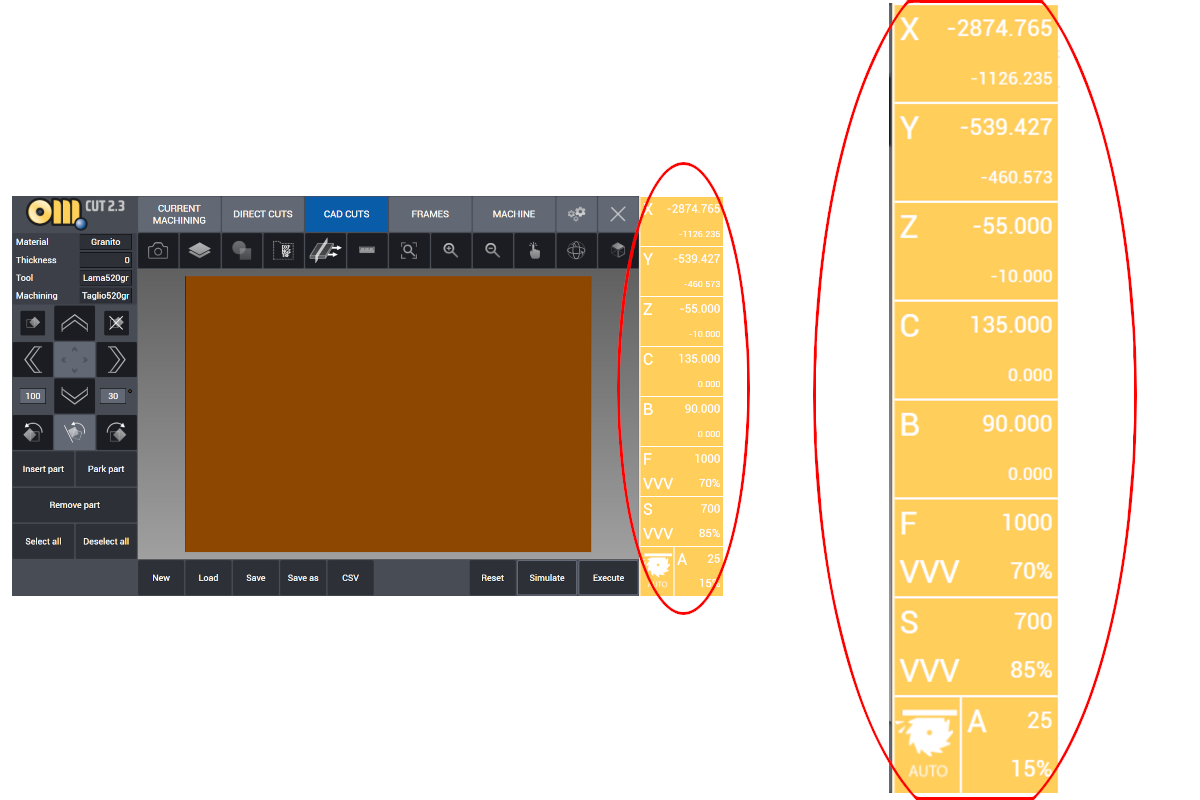
X Y Z are the instant positions of the three axes during the movements and the cut. In each box we find two values: the bigger, upper one represents the real time position, while the smaller value is the desired coordinate to reach. Those coordinates are calculated according to machine absolute zero point.
C B are the istant positions of the rotation axes, expressed in degree.
There are three more boxes under the axes ones:
- Box F: feed (millimiters / minute)
- Box S: rpm (rotations / minute)
- Box A: spindle amperes consumption.
Each one of those boxes display also the relative percentage values.
HOW TO: Create parametric drawings
 As we have seen, this button allows to create parametric geometries whose dimensions can be modified from the user as desired. To add them we have to click on the desired geometry.
 There are some geometries for which is possible to choose between differents sets of parameters in order to create them, by example you can define a triangle giving at your choice 2 segments and the angle between them or giving all three segments. While for others there is no such choice and there is a fixed set of parameters required, for example ellipses have to be defined by Height and Widht.

The interface for editing the parameters contains the value fields on the left: in this column it's possible to modify and specify every parameter for the desired geometry.
The geometric figure is drawn in the middle of the screen. At the bottom the user can give a name to this part and choose the number of parts to be added in cad cuts.
Triangle
There are three way to define a triangle: 

- Two sides and the angle between them.
- Three sides.
- Isosceles triangles with Base and Height.
In the example we have a Isosceles Triangle.
Rectangle
The only way to generate a rectangle is by providing height and lenght. 
Trapezium
There are four ways to define a trapezium: 

- Isosceles: Two bases and the height.
- Right: Two bases and the height.
- Scalene: Two bases, height and one angle
- Scalene: Two bases, height and one side.
In the example we have a Isosceles Trapezium.
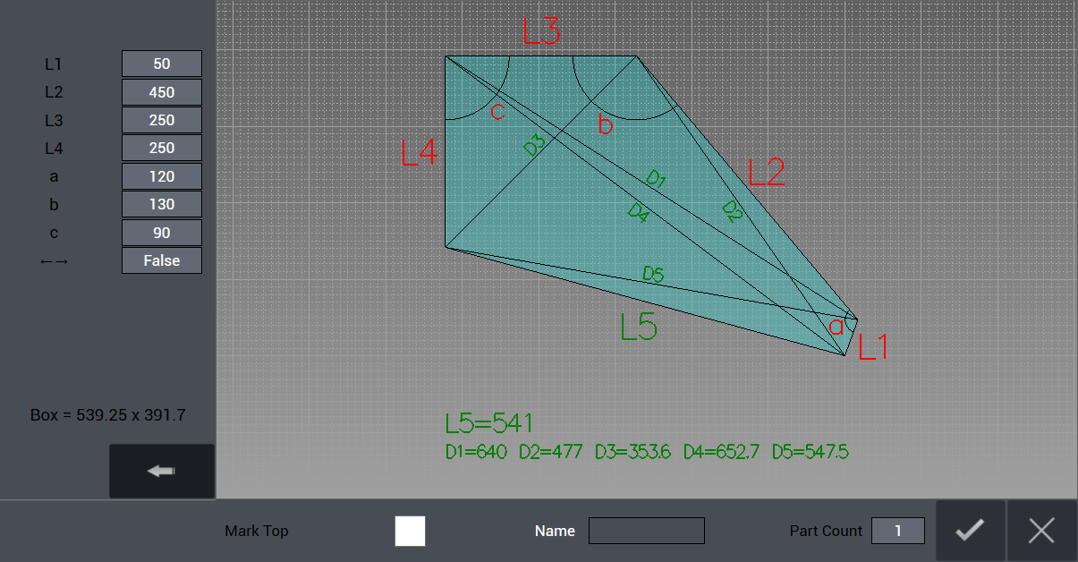
Quadrilateral
There are four ways to define a quadrilateral: 

- Four sides and one angle.
- Four sides and one diagonal.
- Three sides and two angles.
- Three sides and two diagonals.
In the example we have four sides and one diagonal.
Winder
There are three ways to define a winder: 

- Four sides and three diagonals.
- Four sides and three angles.
- Four sides and three angles (different from the previous).
In the example we have four sides and three diagonals
Sill
There is one way to define a sill: 
Giving it all the quotes of the different sides.
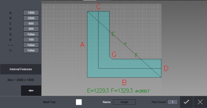
Kitchen Top
There are many ways to define a kitchen top. 

In the example we have the Angle model.
Vanity Top
There are two ways to define a vanity top: 

- Rectangle
- Convex
In the example we have a Convex.
Ellipse
There is one way to define an ellipse: 
Giving it the Height and the Lenght.
Oval
There is one way to define an oval, which is composed by four biarcs: 
Giving it the Height, the Lenght and the curvature parameter.
Arc
There are four ways to define an arc: 

- Giving radius, height and angle
- Lenght, height and parameter F
- Base lenght, top lenght and height
- Base lenght, top lenght and parameter F
In the example we have the LHF option.
Polygon
There is one way to define an polygon: 
Giving it the number of sides, the height from base to the center and the radius from an angle to the center.
Parametric Drawings Examples
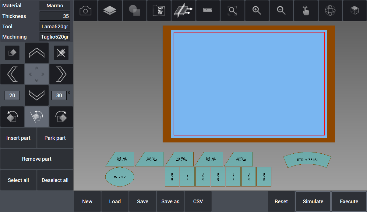
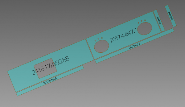
Before starting to cut parts it is necessary to have them positioned inside the slab on the work table.
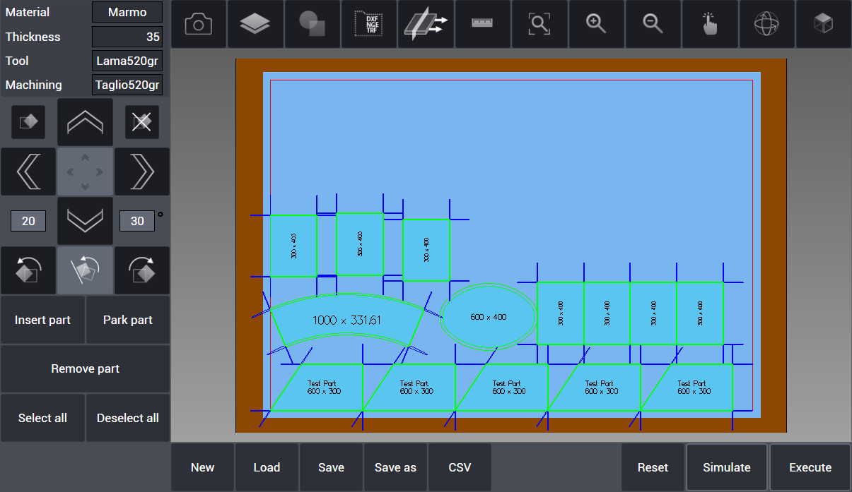
In this example we created some geometries with the Parametric Geometries function. In the first scenario we have all those parts “parked” outside the slab and ready to be organized so the machine can cut them. To do so, use the buttons “Select all” and then “Insert part” so the automatic nesting function can optimise the position of each part. Otherwise it's possible to drag the parts one by one on the slab and position them as preferred, if necessary or if the automatic nesting will not suite the user's needs.
Nesting Options
Whole Cuts Guard On
 Now we have all the parts disposed on the slab ready to be cut. The blue segments coming out from each part's angle represents the cuts guard on the slab. In the MACHINE menù there is the Nesting box that allows to choose the machine behaviour with those cuts guards. If the box is checked every guard prevent the nesting to put another part too close and therefore prevent parts to interfere each others during the cut:
Whole Cuts Guard Off
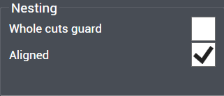 Now to show the different behaviour of the automatic nesting with the Whole cuts guard option (MACHINE Menu) unchecked: the parts are put close to each other without regard for the cuts guards. This can be useful for saving slab material but it is necessary to perform cuts to separate the slab in different parts before doint it so the cuts will not damage the other parts to be cut.
HOW TO: Managing the Machining


We have seen that with the option “Whole Cuts Guard” unchecked the nesting put the parts on the slab each one close to the others to save space on the slab. But this procedure can cause troubles because of the external cuts of the parts on the others. To avoid this problem the user can separate the slab in various parts and set specific movements of those parts with the vacuum in order to create the space needed to avoid cuts problems over other parts.
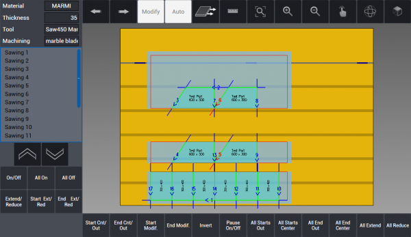
 In the example we have some rectangles and trapezium and the “Whole cuts guard” checkbox is turned off. As we can see there are many cuts that overlap with other parts. In order to perform this machining we will need to separate the slab in different parts and move them with a specific distance so the cuts will not ruin the other parts. We enter in the Machining managing section and we can set how the cuts will be performed.
HOW TO: Configure the cuts
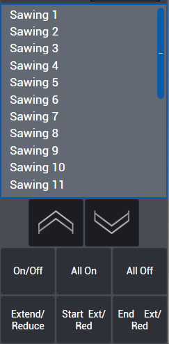 In this box located on the left of the interface are shown the saw cuts numerated (Sawing 1, Sawing 1, …). The sawing order can be modified by using the directional arrow buttons, depending on the preference of the user.
- On/Off: When clicked it deactivate the selected saw cut. Deactivated saw cuts are not performed until they become active by clicking again this button.
- All On: All saw cuts are activated to be executed.
- All Off: All saw cuts are deactivated and will not be executed.
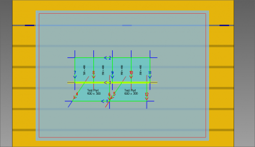 By clicking on the cut 3 it will become selected as in the image. His borders become highlighted in yellow and it is possible now to modify the cut as needed.
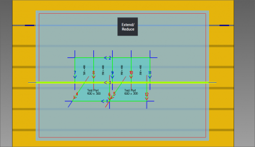 Extend/Reduce: This button allows for extending or reducing the selected saw cut all along the slab, making it starting and ending outside the slab. In this way the slab become divided in two smaller parts that will allow to reduce interference between cuts and parts to be cut.
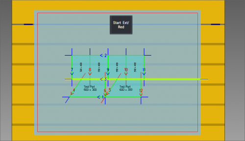 Start Ext/Red: Similar to the Extend/Reduce, but this button only works on the cut from the starting point to outside the slab.
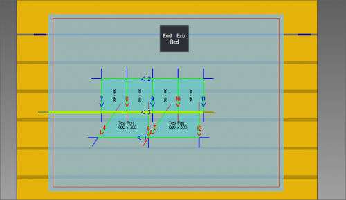 End Ext/Red: Same as Start Ext/Red with the only difference being it does connect the end of the cut (and not the start) to the outside of the slab.
Sawing Management Buttons
At the bottom of this interface, when managing the cuts, there are those buttons:

- Start Cnt/Out: The saw starts to cut directly from its center over the starting point of the line.
- End Cnt/Out: The saw starts the cut directly from its center over the ending point of the line.
- Start Modif.: The user can modify the distance at which the saw starts to cut.
- End Modif.: The user can modify the distance at which the saw ends to cut.
- Invert: It's possible to invert the cutting direction
- Pause On/Off: The machining will pause at the selected cut.
- All starts out: The saw starts every cut directly from its outside over the starting point of the line.
- All starts center: The saw starts every cut directly from its center over the starting point of the line.
- All end out: The saw ends every cut directly from its outside over the ending point of the line.
- All end center: The saw ends every cut directly from its center over the ending point of the line.
- All Extend: Extend to the whole slab every possible cut. Cuts that damage other parts will not be affected.
- All Reduce: Reduce every possible cut to start and end at center of the saw.
 By pressing the “Auto” button, the software will try to perform the most appropiate cut and then separate the slab until there are no cuts interfering with other parts. In the example, there will be done two separating cuts before the others. The vacuum movement system will move the separated parts at a set distance between each others.
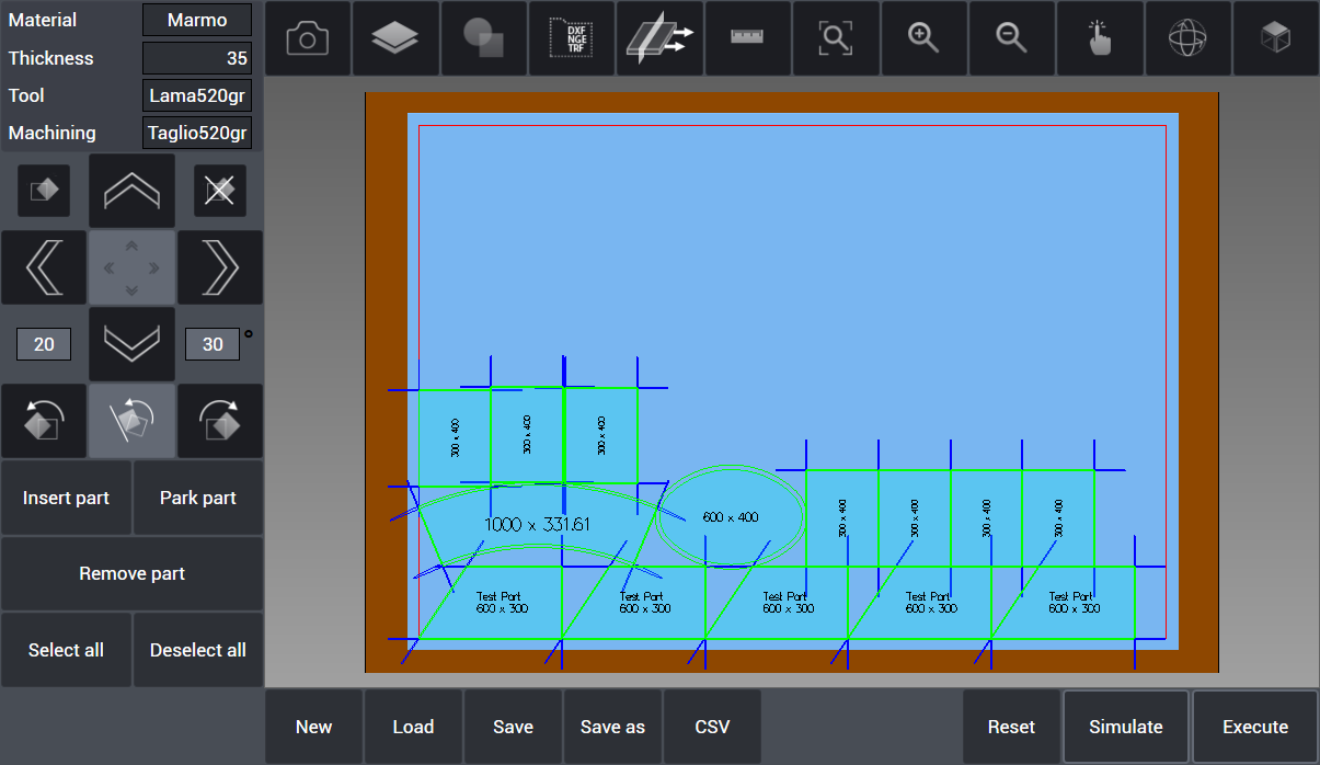
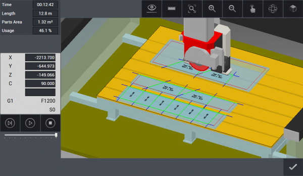
Simulating the Machining
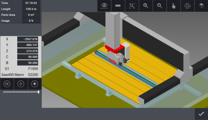
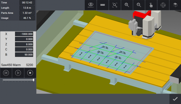 This is the interface when the machining is being simulated. The view become inclusive of the machine and the tool and we can monitor the advancement of the machining before it is executed.
Simulation Info
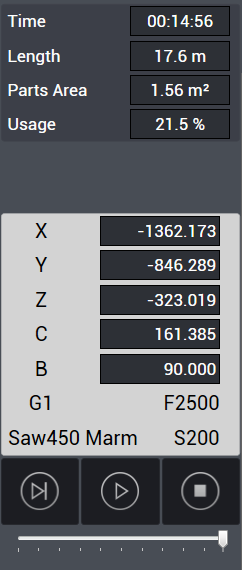 This is the left column during the simulation of the machining:
- Time: estimated machining time from start to finish.
- Lenght: Total cuts lenght on the slab.
- Parts area: Total cut parts surface.
- Usage: Percentage given by the surface of the cut parts to the total slab surface.
- X Y Z: Istant positions of the tool on the three main axis.
- C B: Istant angles of the axis C and B.
- G1: ISO Code of the current machining.
- F2500: Current feed: 2500 mm/min.
- Saw450 Marm: Equipped tool.
- S200: Rotation speed of the tool (200 rpm).
 Next step: simulate only the current tool step.
 Play: start the simulation at the selected speed.
 Stop: stop the simulation.
 Speed: Change the simulation speed from slow to fast.
 Now the simulation is being executed and we can see the first two cuts already done and the parts moved away from each other by the vacuum. This allows for saving slab materials without damaging the parts with the cuts.
HOW TO: Add internal features to parts
 When drawing kitchen and vanity top it is possible to add an internal shape or feature to be cut, depending on the application of that part. By example, kitchen tops can have a rectangle cut in them in order to accomodate a stove top or a washbasin.
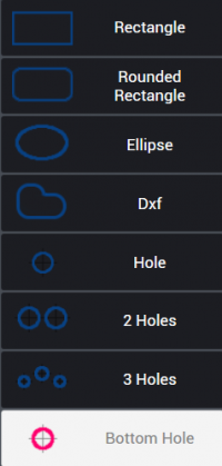 On the left column below the parametric values there is the Internal Features button. By pressing it the Internal Menù will open and the user can choose between different shapes to be cut:
- Rectangle
- Rounded Rectangle
- Ellipse
- Dxf (from file)
- Hole (single)
- Two Holes
- Three Holes
- Bottom Hole
NOTE: Bottom Hole choice is only available if the machine supports it.
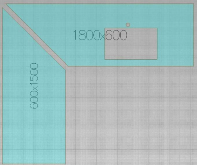
After choosing the shape it is necessary to specify the position on the part and the dimension. This is done thanks to the parameter fields in the left column as shown in the image below. It is possible to add more than one feature on a single part. When the feature is correctly positioned the user press the “Add” button to confirm it.
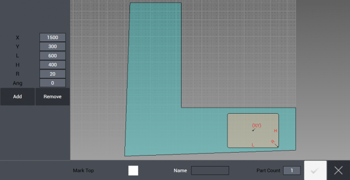
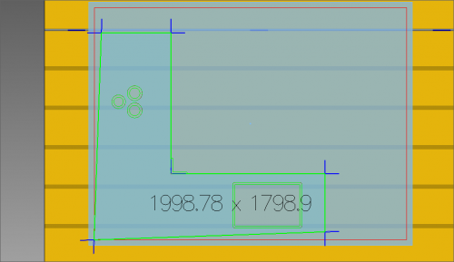 In the example we created a kitchen top with a rounded rectangle on one side (it can be used to accomodate a washbasin) and three holes on the other side (to place fires for cooking) and we placed it on a raw slab ready to be cut. It is possible to add any combination of internal features, the only limit is given by the surface available on the part.
HOW TO: Drilling and cutting sink with 90° corners
 When cutting sink, if sink is rectangular or square with 90° corners, since saw blade is not sufficient to complete the cut, corners are first drilled with drill tools and then sides in between the corners can be cut with saw blade.
Saw blade, auxiliary machining type (only drilling in this case), already defined drill tools that will be used to work the project are selected from the window menu and confirmed. In this example, since sink corners are 90°, saw blade can not enter directly to corners. Therefore, corners are drilled by drill tools so that a much closer result to squareness can be reached.
Holes and Milling parameters
 Under Machine tab, in section Machine data if the checkbox is removed from Single hole in corner, program drills several holes in sequence with respect to parameters defined above instead of drilling a single hole. When doing so it's strongly reccomended to simulate the machining before executing it, as always. By pressing on Simulation button, drilling and saw cutting paths, machine movements are verified and checked in 3D and after each check is realized it's possible to start the machining by pressing Execute.
HOW TO: Add shapes from DXF files
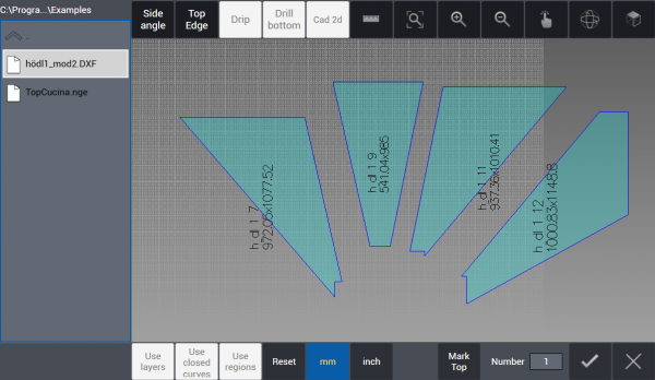 It is possible to select closed geometries by selection button Use closed curves.
With selection button Use regions, it is possible to select a closed curved region subtracting any regions defines by closed curves inside. If there is none internal closed curve within a curve, all geometry is selected as a whole. If preferred, by clicking on Side angle button, parts can be selected one by one and angle values can be assigned to each side of the geometry selected.
It is possible to select closed geometries by selection button Use closed curves.
With selection button Use regions, it is possible to select a closed curved region subtracting any regions defines by closed curves inside. If there is none internal closed curve within a curve, all geometry is selected as a whole. If preferred, by clicking on Side angle button, parts can be selected one by one and angle values can be assigned to each side of the geometry selected.
By clicking on the button with tick icon on low right corner of the page, operation is confirmed and all the parts are added to cutting list as can be seen under work table on main page.
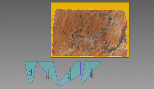
 In the example, we have a DXF file containing a kitchen top and a vanity top, with their sides.
By pressing the Confirm button we import them in our project, then we will place them on the slab in order to have them cut.
 In this scenario we want to cut only the vanity top and its sides.
We select it (note the selected shape's color is different) and we add onto the slab.
In this scenario we want to cut only the vanity top and its sides.
We select it (note the selected shape's color is different) and we add onto the slab.
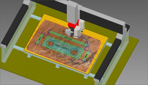 Now the desired parts are disposed on the slab and we are going to simulate the machinery. It's very important to simulate before every execution to check if everything will work without problems.
HOW TO: use Vein Match

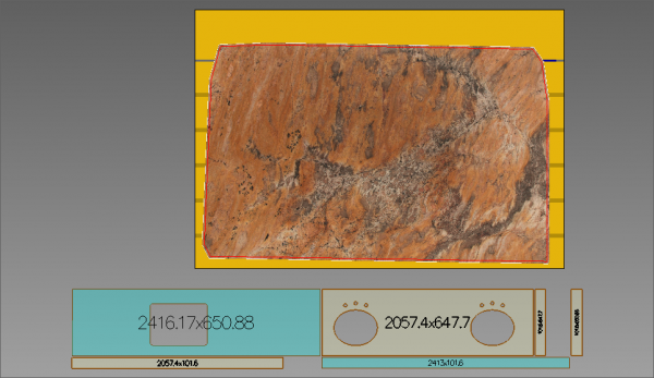
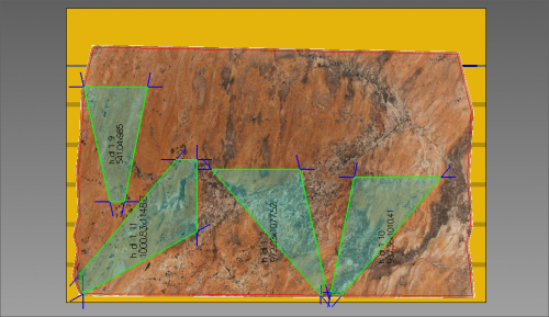
Vein Match allows the positioning of the parts to be cut inside the slab with respect to the veins of the slab using the Camera (Omag Fast Image).
In OMAGCUT programs that include the Vein Match option it is possible to combine the veins between different cuts of slabs and projects. The slab is positioned and its veins photographed on the work surface, then the parts of the project or project on which to match the veins are selected and transported to the main page as a cutting list.
As first step, import at least one part using DXF import function. In the example we have four parts to be cut and we insert them on the slab using the Insert All button:
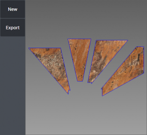
Once the parts are positioned in the slab we press the Vein Match button and in the window that opens you can see the part or parts to be cut organized on the slab.
At this point, click again on the button at the bottom of the page and all parts of the project are displayed in the window that opens.
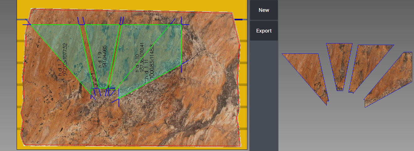
Since the part or parts that are cut from the first slab are kept in the window that opens, it is possible to see the parts that need to be cut on the second slab and, taking into account the correspondence of the veins, they can be moved within the slab.
The Vein Match window can be enlarged and reduced, and the position of the parts to be cut can be changed by dragging them on the slab as usual: the Vein Match window will display the effective veins on the parts that will be cut.
Frames
In this section it's possible to import DXF format files containing a frame profile. It can be worked parametrically along X or Y axes. The import is done by pressing “Section” button on the left column. It is possible to choose a .dxf file containing a frame section.
It's necessary as usual to perform a Raw Stock Definition: See How To: Define New Raw Slab to define the raw slab.
Importing frame profile
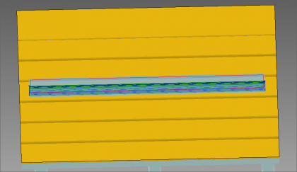
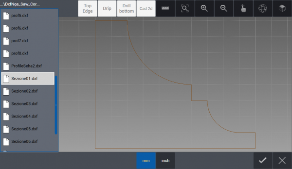 Now we are browsing the folder containing our desired .dxf file (used to load the frame profile). Once it is selected, it is loaded in the current project by pressing the confirmation button on the bottom right of the interface.
 Now the frame profile has been loaded.
- We can choose to work it Along X axis or Along Y axis to change its orientation on the work table.
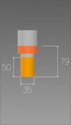
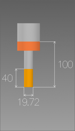
- Top clearance: the portion exempted from cut along Z axis from top plane of the profile.
- Side clearance: the portion exempted from cut along Z axis from top plane of the profile.
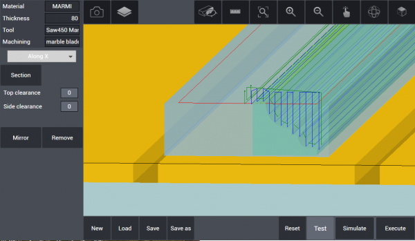
Frame Machining Setup
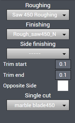
 By clicking the Frame Machining icon a new left column menù appears:
- Roughing is the menu from where the saw blade defined for this operation is selected. Step cut and step size of saw blade are defined in Machining database under the tab Machine (look further subjects).
- Finishing is the menu from where the saw blade defined for this operation is selected. Step cut and step size of saw blade are defined in Machining database under the tab Machine (look further subjects).
- Side finishing is the menu from where the saw blade defined for this operation is selected. Step cut and step size of saw blade are defined in Machining database under the tab Machine (look further subjects).
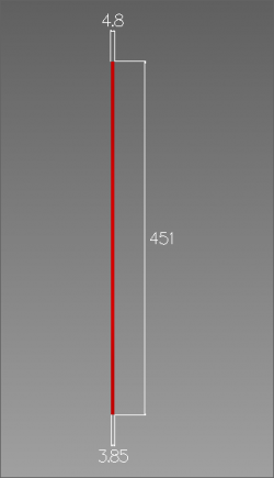
- Trim start defines how much from front the saw blade will start the cut, as an example if entered 10 mm, the saw blade starts the cut from 10 mm inside the profile.
- Trim end defines how much before the end the saw blade will exit the cut, as an example if entered 10 mm, the saw blade exits the cut 10 mm before the end of profile.
- Single cut menu lets select from one to two way cutting methods.
When the parameters are correctly set, it's possible and reccomended to Simulate the machining in order to verify the machine movements. After this check is done the machining can be started by pressing the Execute button.
Machine
In this tab the user can manage most settings of the machine and the tools. Saw, drilling and milling tools are defined according to their dimensions, feed, speed with respect to material type and parameters. For each tool is possible to define different cutting scenarios.
Machine Data
The first section under Machine Menù is “Machine Data”. Here it is possible to define the current tools and machinings as well as Machine parameters, Nesting options and other tools parameters: Saw, Holes, Milling and Engraving parameters.
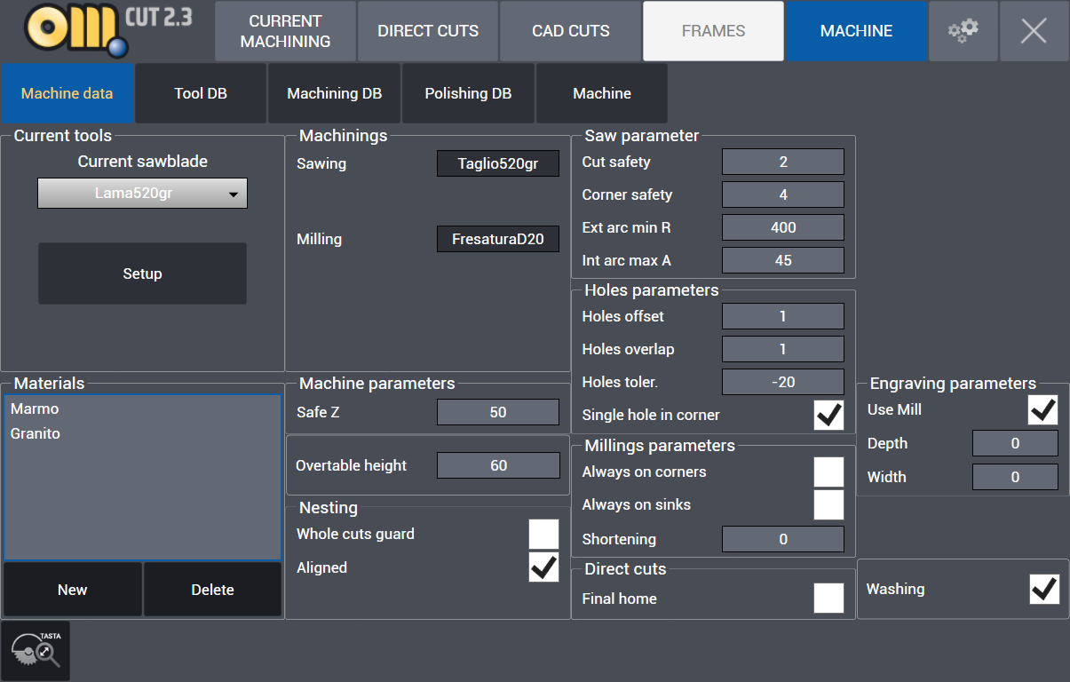
- Current tools: From Current sawblade menu the saw mounted on the machine or the saw to be used is selected and its related parameters are entered.
- Setup : When clicked on Setup button, if machine has auomatic tool change option Automatic or Manual is selected from low left corner of the page that opens:
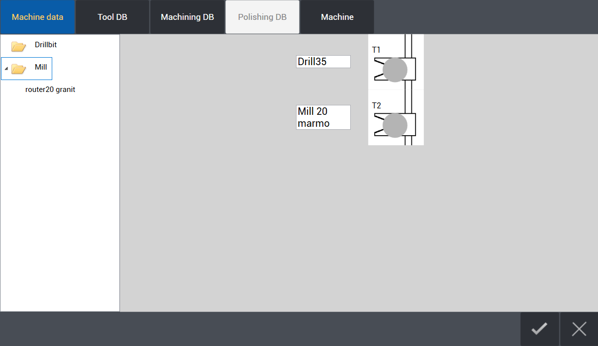
In left menu, there are drilling and milling tools that are already defined. If there is automatic tool change, the tools on left window are dragged to the pod number on right window where they are located really on tool magazine. When time comes to use the tool, either the machine picks up the tool from tool magazine or spindle comes to front for manual attachment.
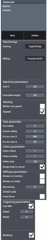
Materials : In Materials menu, all types of materials can be entered and later same or different types of saw blades can be assigned to a material with working parameters specific to that material.
Machinings
- Sawing: Display the current Sawing tool
- Milling: Display the current milling tool
Machine parameters
- Safe Z : Safe approach value in vertical Z.
- Overtable height : Height of shim or wood measured over top of work table.
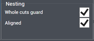
Nesting
- Whole cuts guard : Preference of whole cuts guard
- Aligned : Preference of nesting with magnetic attachment function active
Saw parameter
- Cut safety : Safe height value over material from where cut starts.
- Corner safety : Safe approach value to a corner
- Ext arc min R : Minimum radius value of external arc that can be cut
- Int arc max A : Internal arc maximum angle value
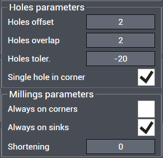
Holes parameters
- Holes offset : Offset value of hole or holes from corner
- Holes overlap: Overlap value of holes in case more than one hole
- Holes toler. : Hole tolerance value
- Single hole in corner : Preference of only one single hole to be drilled in corners
Milling parameters
- Always on corners : Preference of milling always on corners
- Always on sinks : Preference of milling always on sinks
- Shortening : Amount of distance value to be shortened on milling path
Direct cuts
- Final home : Preference of return to home position after cut
Engraving Parameters
- Use Mill: Choose to use or not use Milling tools for engraving.
- Depth: Maximum Depth of the engravings.
- Width: Width of the engravings.
Washing : Preference of washing before vacuum lifting operation of parts
Tool DB
Under the Tool DB it is possible to declare, modify and add any tool we are going to use:
- Sawblade
- Drillbit
- Mill
- Polishing Wheel
for each tool is then possible to configure its parameters: dimension, speed, feed and position.
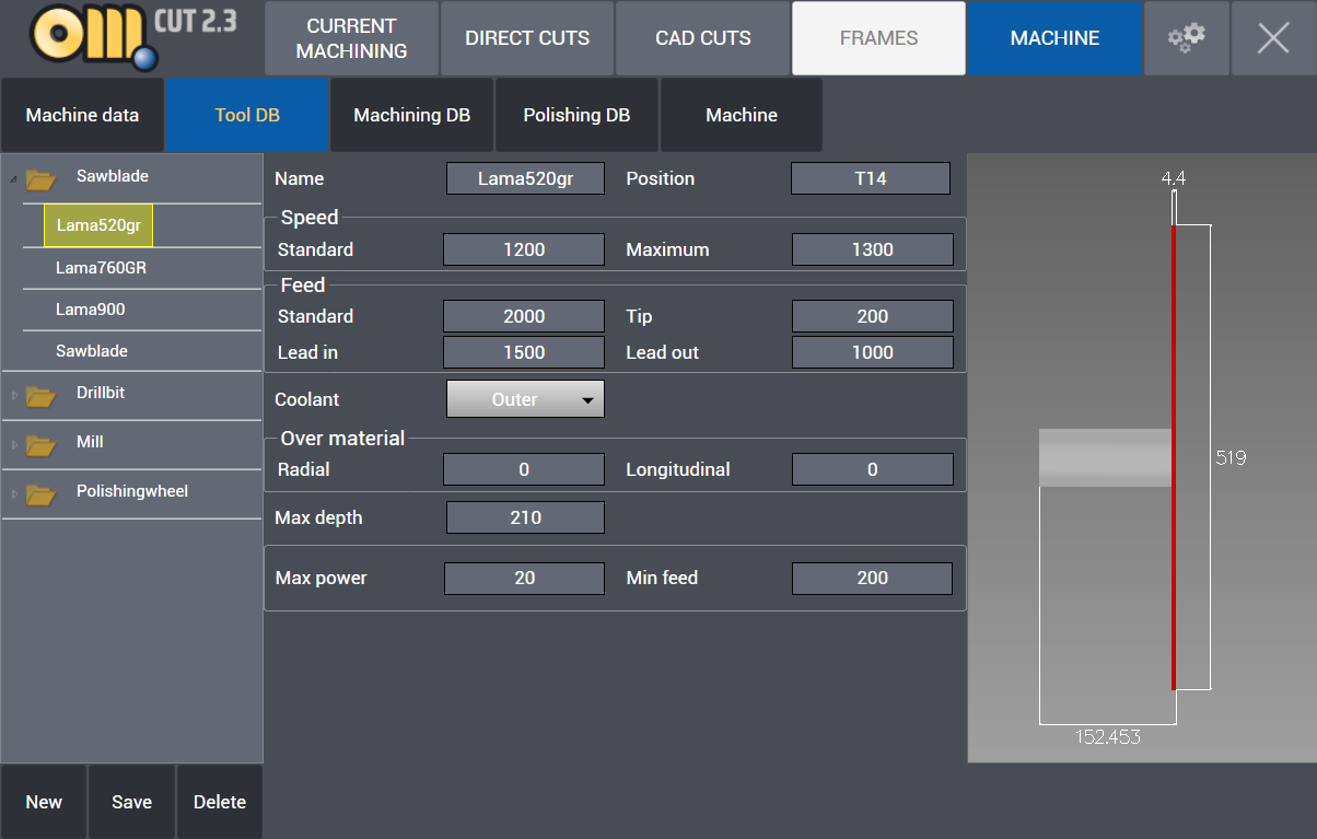
In the bottome left there are buttons wich make possible to define a new tool.
By clicking on New button a page for Sawblade parameters is opened on right side. By clicking Save it is saved and by clicking Delete the selected tool is deleted.
SAWBLADE
- Name : Name of saw blade is entered.
- Position : Saw blade position number, if it is on a tool magazine, magazine pod number is entered.
Speed
- Standard : Working rpm (rotations / minute) value is entered.
- Maximum : Maximum rpm (rotations / minute) value is entered.
Feed
- Standard : Work feed value (mm / minute)
- Tip : Head feed value (mm / minute)
- Lead in : Lead in feed value (mm / minute)
- Lead out: Lead out feed value (mm / minute)
- Coolant : No / Outer coolant preference
Over material
- Radial : Excess material thickness deliberately left on the piece in a radial direction
- Longitudinal : Excess material thickness deliberately left on the piece in a longitudinal direction
- Max depth : Maximum thickness value that saw blade can cut (mm).
- Max power : Maximum amperes consumption allowed.
- Min feed : Minimum feed value (mm / minute)
DRILLBIT
Name : Name of drill is entered. Speed
- Standard : Working rpm (rotations / minute) value is entered.
- Maximum : Maximum rpm (rotations / minute) value is entered.
Feed
- Standard : Work feed value (mm / minute)
- Tip : Head feed value (mm / minute)
- Lead in : Lead in feed value (mm / minute)
- Lead out: Lead out feed value (mm / minute)
- Coolant : No / Inner / Outer / Both coolant preference
- Max power : Maximum amperes consumption allowed.
- Min feed : Minimum feed value (mm / minute)
MILL
Name : Name of milling tool is entered.
Speed
- Standard : Working rpm (rotations / minute) value is entered.
- Maximum : Maximum rpm (rotations / minute) value is entered.
Feed
- Standard : Work feed value (mm / minute)
- Tip : Head feed value (mm / minute)
- Lead in : Lead in feed value (mm / minute)
- Lead out: Lead out feed value (mm / minute)
- Coolant : No / Inner / Outer / Both coolant preference
Over material
- Radial : Excess material thickness deliberately left on the piece in a radial direction
- Longitudinal : Excess material thickness deliberately left on the piece in a longitudinal direction
- Max power : Maximum amperes consumption allowed
- Min feed : Minimum feed value (mm / minute)
Machining DB
The Machining DB page allow the definition of different kind of Machining. For each type there is a different set of parameters that can be defined, along with the suitable material for that machining.
SAWING
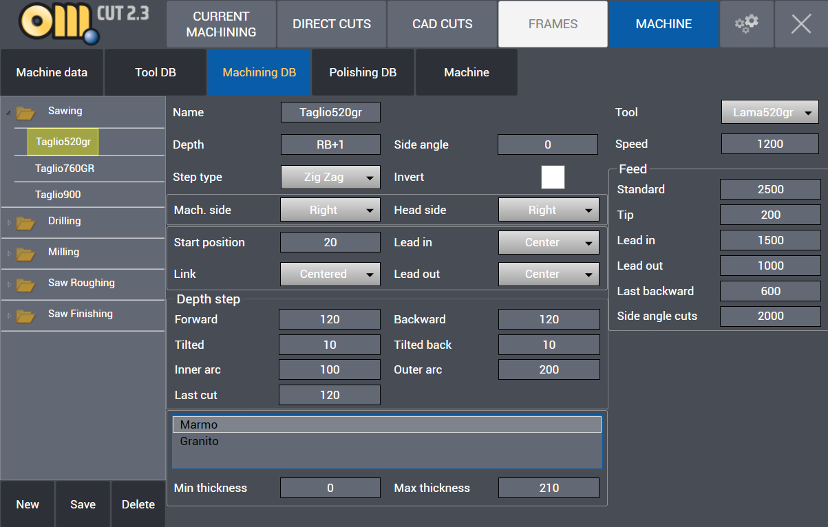
- Name : Name of machining is entered.
- Depth : RB is automatically the thickness value of the part to be cut which is normally cutting depth in mm. RB+2 means cutting depth will be 2 mm more in addition to thickness of the part.
- Side angle : Different than the side angle that can be assigned parametrically, a specific side angle value can be assigned to machining.
- Step type : Zigzag – One way – Back and forth type cutting can be selected for the machining.
- Invert : It inverts direction of motor during cutting.
- Mach. side : It selects cutting side of saw blade, Center – Left – Right can be selected.
- Head side : Head side of cutting, Left – Right can be selected.
- Start position : Distance value over the material where the cut starts.
- Lead in type : Centered – Inner – Outer – Cent. Extended – Outer Extended Lead in types can be selected.
- Link type : Centered – Prev Extended – Next Extended – Both Extended link types between cutting paths can be selected.
- Lead out type : Centered – Inner – Outer Lead out types can be selected.
Depth step
- Forward : It is forward step value in mm in step cutting.
- Backward : It is backwards step value in mm in step cutting.
- Tilted : It is forward step value in mm in angle step cutting.
- Tilted back : It is backwards step value in mm in angle step cutting.
- Inner arc : Inner arc step cutting value in mm.
- Outer arc : Outer arc step cutting value in mm.
- Material : Material type which machining is assigned to.
- Min thickness: Minimum cutting thickness
- Max thickness: Maximum cutting thickness
- Tool : Tool which machining is assigned to.
- Speed : Working rpm (rotations / minute) value is entered.
Feed
- Standard : Work feed value (mm / minute)
- Tip : Head feed value (mm / minute)
- Lead in : Lead in feed value (mm / minute)
- Lead out: Lead out feed value (mm / minute)
- Last backward : last cut backwards feed value (mm / minute)
DRILLING
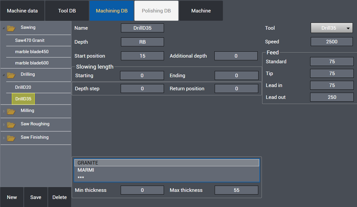
- Name : Name of machining is entered.
- Depth : RB is automatically the thickness value of the part to be cut which is normally drilling depth in mm. RB+1 means drilling depth will be 1 mm more in addition to thickness of the part.
- Start position : Height value over the material where the drill feed starts.
- Additional depth : It is the additional depth value the drill continues under the slab.
Slowing length
- Starting : It indicates the distance with slow feed at start of the drill.
- Ending : It indicates the distance to the end of drill with slow feed.
- Depth step : If drilling is step, it indicates the drill step value, if there is no step, value is entered 0.
- Return position : If drilling is step, it indicates upwards movement value of drill before next step.
- Material : Material type which machining is assigned to.
- Min thickness: Minimum drilling thickness
- Max thickness: Maximum drilling thickness
- Tool : Tool which machining is assigned to.
- Speed : Working rpm (rotations / minute) value is entered.
Feed
- Standard : Work feed value (mm / minute)
- Tip : Head feed value (mm / minute)
- Lead in : Lead in feed value (mm / minute)
- Lead out: Lead out feed value (mm / minute)
MILLING
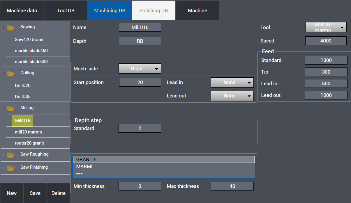
- Name : Name of machining is entered.
- Depth : RB is automatically the thickness value of the part to be cut which is normally milling depth in mm. RB+1 means milling depth will be 1 mm more in addition to thickness of the part.
- Mach. side : It selects cutting side of milling tool, Center – Left – Right can be selected.
- Start position : Height value over the material where the mill feed starts.
- Lead in type : Centered – Inner – Outer – Cent. Extended – Outer Extended Lead in types can be selected.
- Lead out type : Centered – Inner – Outer Lead out types can be selected.
Depth step
- Standard: If milling is step, it indicates the milling step value, if there is no step, value is entered 0.
- Material : Material type which machining is assigned to.
- Min thickness: Minimum milling thickness
- Max thickness: Maximum milling thickness
- Tool : Tool which machining is assigned to.
- Speed : Working rpm (rotations / minute) value is entered.
Feed
- Standard : Work feed value (mm / minute)
- Tip : Head feed value (mm / minute)
- Lead in : Lead in feed value (mm / minute)
- Lead out: Lead out feed value (mm / minute)
SAW ROUGHING
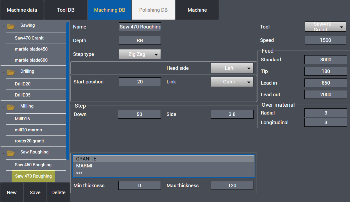
- Name : Name of machining is entered.
- Depth : RB is automatically the thickness value of the part to be cut which is normally sawing depth in mm. RB+1 means sawing depth will be 1 mm more in addition to thickness of the part.
- Step type : Zigzag – One way – Back and forth type cutting can be selected for the machining.
- Head side : Head side of cutting, Left – Right can be selected.
- Start position : Distance value over the material where the cut starts.
- Link type : Centered – Prev Extended – Next Extended – Both Extended link types between cutting paths can be selected.
Step
- Down : Downwards Z step value in mm in saw roughing.
- Side : Side roughing step value in mm in saw roughing.
- Material : Material type which machining is assigned to.
- Min thickness: Minimum cutting thickness
- Max thickness: Maximum cutting thickness
- Tool : Tool which machining is assigned to.
- Speed : Working rpm (rotations / minute) value is entered.
Feed
- Standard : Work feed value (mm / minute)
- Tip : Head feed value (mm / minute)
- Lead in : Lead in feed value (mm / minute)
- Lead out: Lead out feed value (mm / minute)
Over material
- Radial : Excess material thickness deliberately left on the piece in a radial direction
- Longitudinal : Excess material thickness deliberately left on the piece in a longitudinal direction
SAW FINISHING
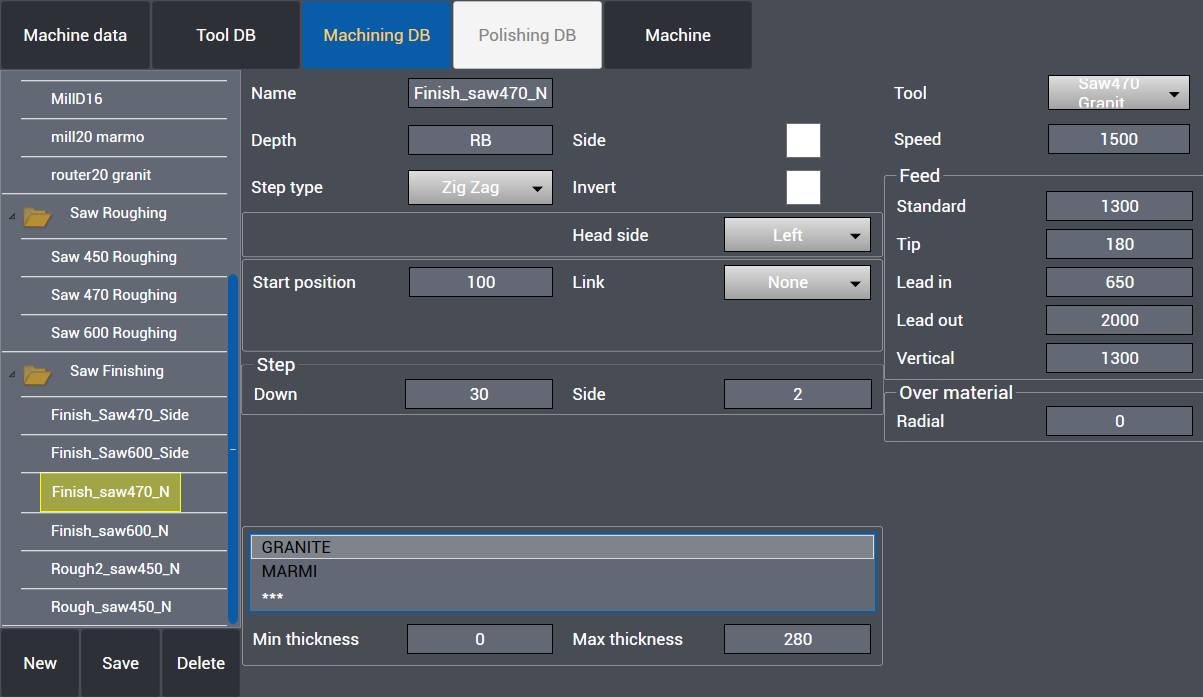
- Name : Name of machining is entered.
- Depth : RB is automatically the thickness value of the part to be cut which is normally sawing depth in mm. RB+1 means sawing depth will be 1 mm more in addition to thickness of the part.
- Step type : Zigzag – One way – Back and forth type cutting can be selected for the machining.
- Side : Preferred for transversal cutting.
- Invert : It inverts direction of motor during cutting.
- Head side : Head side of cutting, Left – Right can be selected.
- Start position : Distance value over the material where the cut starts.
- Link type : Standard - Centered – Outer link types between cutting paths can be selected.
Step
- Down : Downwards Z step value in mm in saw roughing.
- Side : Side roughing step value in mm in saw roughing.
- Material : Material type which machining is assigned to.
- Min thickness: Minimum cutting thickness
- Max thickness: Maximum cutting thickness
- Tool : Tool which machining is assigned to.
- Speed : Working rpm (rotations / minute) value is entered.
Feed
- Standard : Work feed value (mm / minute)
- Tip : Head feed value (mm / minute)
- Lead in : Lead in feed value (mm / minute)
- Lead out : Lead out feed value (mm / minute)
- Vertical : Vertical work feed value (mm /minute)
Over material
- Radial : Excess material thickness deliberately left on the piece in a radial direction
Polishing DB
The Polishing DB Page allows to configure and customize how the machine execute the polishing on the slab.
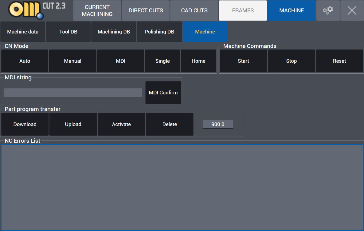
Machine
CN mode
Auto – Manual – MDI - Single - Home commands can be executed in CN mode.
Machine Commands: Start – Stop – Reset commands can be executed.
MDI string: Single line machinery commands and M functions can be activated through MDI interface.
Part program transfer : Cn program transfer commands Download– Upload – Activate– Delete commands can be executed.
NC Errors List can be viewed as registered.
Settings
By clicking the gear icon the user enter the software settings. Here can be modified the language and the unit of measure.
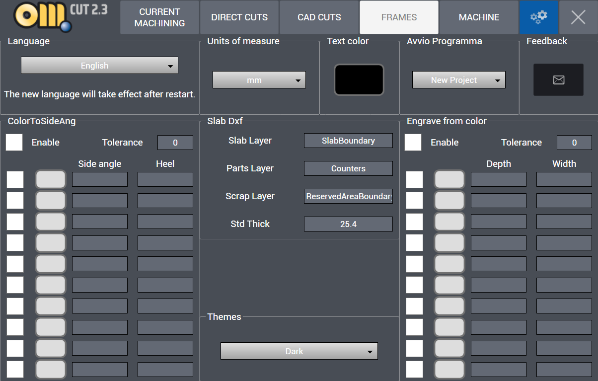
Color To Side Ang: In fase di importazione di disegni 2D assegna l'inclinazione e il tallone in funzione del colore assegnato.
Engrave from color: In fase di importazione di disegni 2D assegna la profondità e lo spessore in funzione del colore assegnato.
X
Click the final “X” in this tab in order to close the OMAGCut application.